

Designing an ATC for Limited Installation Space: Key Factors for Machine Tool Builders
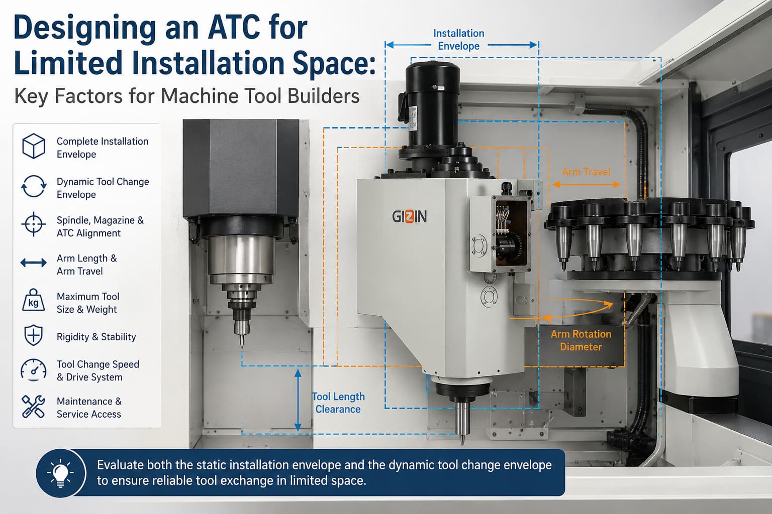
When installation space is limited, machine tool builders should not select an automatic tool changer based only on tool capacity or tool change speed. The first priority is to confirm whether the complete ATC envelope—including the cam box, tool changer arm, motor, sensors, mounting structure, tool magazine, and moving tools—can operate without interfering with the spindle, machine enclosure, guarding, cables, piping, or other machine components.
A smaller ATC does not automatically solve the problem. Reducing the mechanism or shortening the tool changer arm may affect tool clearance, structural rigidity, motion stability, and compatibility with the required tool size and weight. Machine builders must therefore evaluate the ATC’s physical dimensions together with its complete tool change path.
The most important factors are the available installation envelope, spindle and magazine positions, arm travel, arm length, tool swing diameter, maximum tool weight, mounting direction, service clearance, and target tool change time. Confirming these requirements early can reduce redesign work and help the ATC fit the machine without compromising reliable tool exchange.
If you are currently evaluating an ATC for a space-constrained machine layout, share your available installation dimensions, spindle interface, magazine position, and maximum tool specifications with our engineering team. Contact GIZIN to discuss the initial requirements before finalizing your machine design.
Why Limited Installation Space Creates More Than a Size Problem
Compact CNC machines are increasingly used where floor space, shipping dimensions, or production-cell layouts must be controlled. However, fitting more functions into a smaller machine enclosure creates greater integration challenges for the automatic tool changer.
The ATC is not a stationary component. During a tool change, the arm must approach the spindle and magazine, grip both tools, remove them, rotate, insert them into the opposite positions, and return to its home position. The required space is therefore larger than the external dimensions of the cam box alone.
A system may appear to fit in a static machine layout but still experience interference when the arm begins moving or when a long or large-diameter tool is installed. This is why machine builders must evaluate both the fixed installation envelope and the dynamic motion envelope.
1. Define the Complete ATC Installation Envelope
The first step is to identify the actual three-dimensional space available for the ATC.
This evaluation should include:
- Cam box width, height, and depth
- Drive motor and electrical connection space
- Sensor and encoder locations
- Tool changer arm length and rotation range
- Mounting brackets and fasteners
- Tool magazine interface
- Machine guarding and enclosure panels
- Cable, pneumatic line, and lubrication line routing
- Access required for installation and maintenance
Focusing only on the main ATC body can lead to unexpected interference during machine assembly. Connectors, covers, brackets, and service access points may occupy additional space that was not considered in the initial layout.
Machine builders should also identify which surrounding components are fixed and which can be repositioned. In some projects, adjusting the magazine position, motor orientation, guarding shape, or mounting structure may provide a more practical solution than reducing the size of the ATC mechanism itself.
2. Check the Dynamic Tool Change Envelope
The dynamic envelope is the total space used by the arm, grippers, tool holders, and cutting tools throughout the entire tool change sequence.
Machine builders should check the movement at every stage:
- Arm movement toward the spindle and magazine
- Gripper engagement with both tool holders
- Tool extraction from the spindle and magazine pot
- Arm rotation with two tools
- Tool insertion into the spindle and magazine
- Arm return to the home position
This check should use the largest and longest tools expected on the machine—not only a standard tool holder. Tool diameter, gauge length, holder geometry, and adjacent tool positions can all affect the required clearance.
If the machine will handle oversized tools, the design may require empty magazine pockets next to those tools. This reduces effective magazine capacity and should be considered when defining the machine specification.
3. Confirm Spindle, Magazine, and ATC Alignment
Limited space leaves less room to compensate for alignment problems. The spindle tool change position, magazine exchange position, and ATC mounting position must be coordinated accurately.
Important dimensions include:
- Distance between the spindle and magazine exchange point
- Spindle center height
- Magazine pot orientation
- Tool holder gripping position
- Arm travel
- Arm rotation radius
- Tool extraction distance
- Allowable mounting angle
- Spindle orientation requirements
These dimensions determine whether the tool changer arm can grip, remove, rotate, and insert the tools correctly.
A change to one part of the machine layout can affect several other dimensions. For example, moving the magazine closer to save space may reduce clearance for arm rotation or maintenance. Moving the ATC upward may avoid interference with the enclosure but create a new conflict with the motor or overhead structure.
The spindle, magazine, and ATC should therefore be reviewed as one integrated system rather than as separate components.
4. Select the Correct Arm Length and Arm Travel
The tool changer arm must be long enough to connect the spindle and magazine positions, but unnecessary arm length increases the motion envelope and may create additional structural demands.
A longer arm can:
- Require more rotational clearance
- Increase the effect of tool weight on the mechanism
- Place greater loads on the arm and grippers
- Increase sensitivity to vibration during high-speed motion
A shorter arm creates a more compact movement path, but only if the spindle and magazine can be positioned sufficiently close together. Shortening the arm without reviewing the machine layout may result in insufficient reach or interference during tool removal and insertion.
Arm travel must also match the spindle and magazine interface. Too little travel may prevent complete tool extraction, while excessive travel may occupy unnecessary space or affect the tool change cycle.
GIZIN offers ATC platforms with different arm travel and arm length ranges for different spindle tapers and machine configurations. Machine builders should compare these dimensions with their machine layout before selecting a model.
5. Evaluate Maximum Tool Size and Weight
The available installation space cannot be evaluated independently from the tools the machine must handle.
A compact ATC for lighter tools has different requirements from a system designed for long, large-diameter, or heavy tools. Machine builders should provide information such as:
- Spindle taper
- Tool holder standard
- Maximum tool diameter
- Maximum tool length
- Maximum tool weight
- Combined load carried by the arm
- Tool center-of-gravity position
- Oversized-tool requirements
Tool weight affects the arm structure, gripper design, cam mechanism, drive requirements, and motion profile. Tool length and diameter affect the swing path and surrounding clearance.
The center of gravity is also important. Two tools with the same weight can apply different loads if one projects much farther from the gripper. For this reason, maximum tool weight alone may not provide enough information for ATC evaluation. For a more detailed explanation, see How Tool Weight, Length, and Balance Affect ATC Tool Change Safety.
6. Do Not Sacrifice Rigidity Only to Reduce Size
When space is restricted, it may be tempting to reduce the thickness or size of structural parts. However, excessive weight or material reduction may lower rigidity and affect motion stability.
During tool exchange, the arm experiences acceleration, deceleration, rotation, and the combined load of two tools. The structure must remain stable through the complete cycle.
A compact design should maintain:
- Sufficient arm rigidity
- Secure tool gripping
- Stable cam-driven motion
- Proper bearing and shaft support
- Controlled acceleration and deceleration
- Repeatable positioning at the spindle and magazine
The goal is not to make every component as small as possible. It is to use the available space efficiently while maintaining the mechanical performance required by the application.
For more information about the mechanism controlling ATC motion, read How a High-Precision Cam Box Improves CNC Tool Change Speed and Reliability.
7. Balance Tool Change Speed with Available Space
Tool change speed is important, but it should not be considered separately from tool weight, arm length, machine rigidity, and available clearance.
Faster motion can increase acceleration and deceleration loads. In a compact machine, there may also be less clearance available to absorb vibration or accommodate movement around nearby components.
The shortest published cycle time is therefore not automatically the best choice for every machine. A more useful question is:
What tool change time can the complete system achieve reliably with the required tool size, tool weight, arm length, and installation layout?
The drive method also affects how the motion can be controlled. Depending on the machine requirements, an electric motor or servo motor may be selected. Machine builders can review the differences in Electric Motor vs. Servo Motor ATC Systems: Which Drive Method Is Best for Your Machine Tool?
8. Reserve Space for Installation and Maintenance
A layout that leaves no unused space may look efficient in a CAD model, but it can create difficulties during assembly, inspection, adjustment, and maintenance.
Machine builders should reserve access for:
- Mounting and removing the ATC
- Checking sensors or encoders
- Inspecting the tool changer arm and grippers
- Accessing lubrication points
- Checking fasteners and connections
- Removing covers
- Routing or replacing electrical cables
- Inspecting the drive motor
- Performing alignment adjustments
The machine enclosure should also allow technicians to reach the ATC safely without removing several unrelated components.
Service access is especially important for machines exported to overseas markets. A system that is difficult to inspect or disassemble can increase service time and complicate communication between the machine builder, local service team, and end user.
9. Review the Layout Before the Machine Design Is Finalized
ATC selection should begin during the machine layout stage—not after the spindle, magazine, guarding, and enclosure have already been fixed.
Early coordination allows the machine builder and ATC supplier to review:
- Available installation dimensions
- Spindle and magazine locations
- Tool change positions
- Required arm movement
- Maximum tool specifications
- Drive and sensor options
- Mounting direction
- Interference risks
- Target cycle time
- Maintenance access
A three-dimensional interference review or motion simulation can help identify problems before physical parts are manufactured. It should include the ATC mechanism, maximum tool envelope, magazine, spindle, guarding, cables, piping, and nearby machine structures.
This process does not replace physical validation, but it can reduce avoidable design changes during assembly and testing.
10. Determine Whether a Standard Platform Can Be Adapted
Limited installation space does not always require a completely new ATC.
A practical starting point is to compare the machine requirements with existing ATC platforms. Depending on the project, it may be possible to adapt elements such as:
- Arm length
- Mounting configuration
- Motor or sensor arrangement
- External interface
- Tool handling requirements
- Selected structural components
Using a proven platform can reduce development risk while still allowing important interfaces to match the machine.
However, not every requested dimension can be changed independently. Modifying one part may affect rigidity, motion geometry, load capacity, manufacturing feasibility, or tool change time. The design must therefore be evaluated as a complete mechanical system.
For a broader explanation of this approach, see Finding the Right Custom Horizontal Automatic Tool Changer for Your HMC.
Information to Prepare Before Discussing an ATC Project
Providing complete information early helps the ATC supplier evaluate the project more accurately.
Machine builders should prepare:
- Machine type and overall layout
- Available ATC installation envelope
- Spindle taper and tool holder standard
- Spindle tool change position
- Magazine type and exchange position
- Maximum tool diameter, length, and weight
- Distance between spindle and magazine
- Required arm travel and approximate arm length
- Target tool change time
- Preferred drive system
- Sensor or encoder requirements
- Mounting direction
- Guarding and enclosure restrictions
- Maintenance access requirements
- 2D drawings or 3D layout files when available
These details make it easier to identify potential interference, compare suitable ATC platforms, and determine which areas may require adjustment.
Conclusion
Designing an ATC for limited installation space is not simply a matter of choosing the smallest available unit. The complete tool change system must fit the machine while providing sufficient clearance, structural rigidity, tool capacity, motion stability, and maintenance access.
The key is to evaluate both the static installation envelope and the dynamic tool change envelope early in the machine design process. Spindle position, magazine location, arm travel, arm length, maximum tool dimensions, mounting arrangement, drive method, and service clearance should all be reviewed together.
Founded in 2001, GIZIN specializes in automatic tool changers for CNC machine tools and supplies vertical, horizontal, and customized ATC products. By combining established ATC platforms with project-specific engineering evaluation, GIZIN helps machine tool builders identify a suitable integration direction for different machine layouts and tool-changing requirements.
Discuss Your ATC Layout with GIZIN
Share your machine layout, spindle interface, magazine position, available installation space, maximum tool specifications, and target tool change time with the GIZIN engineering team. We can help evaluate a suitable ATC platform and identify the key dimensions that should be confirmed before your machine design is finalized.
Related Articles
- Finding the Right Custom Horizontal Automatic Tool Changer for Your HMC
- Why Machine Tool Builders Source ATC Cam Boxes from Specialized Manufacturers
- How a High-Precision Cam Box Improves CNC Tool Change Speed and Reliability
- Electric Motor vs. Servo Motor ATC Systems: Which Drive Method Is Best for Your Machine Tool?